Summary
This article will briefly outline the basic arrangement that can be used as guidance for your DIY RC electronics.
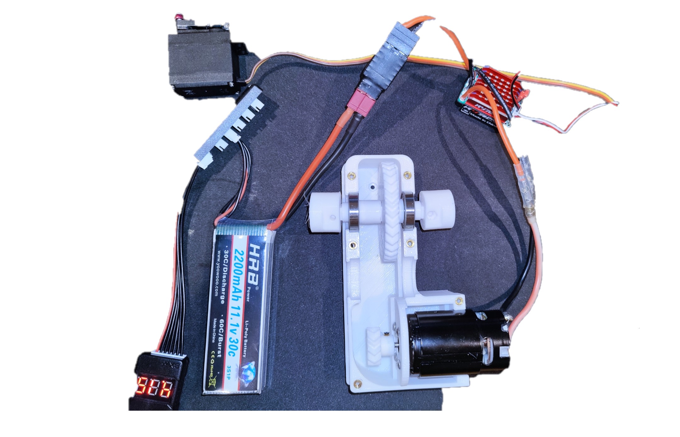
Parts List
Any of these specific parts that are mentioned here can be interchanged for your specific needs. The list of parts outlined is the minimum number of components to have a functioning motor and servo.
| Component | Part No. |
|---|---|
| Radio Controller/Transmitter | FS-GT5 |
| Radio Reciever | FS-BS6 |
| Electronic Speed Controller (ESC) | KYRC X60 - Brush |
| Battery Eliminator Circuit (BEC) | KYRC X60 - Brush |
| Lipo Voltage Indicator | BX100 |
| Brushed/Brushless Motor | 550/35T Brushed Motor |
| Servo | MG-996R |
| LiPo Battery | 11.1V 3S HRB Power |
| Battery Balance Charger/Discharger | HTRC T150 |
Type of Electrical Connectors
These are the electrical connectors used in these components.
| Component | Connector(s) |
|---|---|
| ESC | Traxxas, Deans, Motor Pin, Futaba |
| Battery | Traxxas, Deans |
| Motor | Motor Pin |
| Servo | Futaba |
| Voltage Alarm | JST XH |
| Balance Charger | JST XH |
Typically the battery connectors can come in a number of varieties which can make the matter confusing. However, you always have the option of hooking up and adapter.
In my case, I had to use as Deans (male) to Traxxas (female) adapter to complete the circuit.
Block Diagram - Connections
Here is the component block diagram:
The ESC as the hub of the system in which everything connects to. The ESC on my system also happens perform the functionality of the BEC and can be considered as one unit.
Radio
My radio Rx/Tx system came as a package, and were already “bound” together already. As long as I could supply a current to the receiver, it automatically connect to the transmitter.
If you do not have binding (or need to use a new receiver), there are usually specific procedures to follow for your given controller to bind them together (in the manual for the controller).
There are no complicated procedures outside of this, you just need to follow the block diagram and make sure the components are rated for the supplied voltage/current.
The radio transmitter I used has 6 channels.
For reference my servo was plugged into Channel 1 (CH1), my ESC/Motor was plugged into Channel 2 (CH2).
There are still 4 empty channels open for other electronics such as additional servos can supplement your RC controls.
LiPo Battery Maintenance
Safety Precautions should be taken when using LiPo batteries, they can be very dangerous if mishandled.
Storage
If you are not using the LiPo’s when they are in a “charged” state, then you should consider discharging them to a “storage voltage”. A safe storage voltage per cell is somewhere between 3.6V and 3.8V.
Charging
The maximum allowable voltage of a LiPo cell is 4.2V per cell. Do not overcharge the battery as you may cause damage to the battery and reduce the lifespan; it may also become a fire hazard if consistently overcharged.
In terms of charging rates, I am charging my batteries at a rate of 1C. For a 2200mAH battery this equates to 2.2A.
Discharging
The inverse is true about discharging the battery too much. Do not let the LiPo voltage fall below 3.2V per cell as this will also cause internal damage to the battery which is irreversible. To mitigate this risk, you can use a voltage alarm on your circuit to warn you when the voltage is falling below a desired threshold.
Signs to Discontinue Battery Usage
A well maintained LiPo battery should be able to safely achieve at least 300 full charge/discharge cycles if obeying the precautions above.
There are a list of signals decide whether or not to discontinue use of any given LiPo:
- If you see ballooning occur in the battery.
- Battery not holding a charge and voltage drop-off.
- Battery getting warm when charging at a rate of 1C.
- Physical dents or damage to the battery increasing the internal resistance.
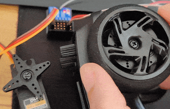
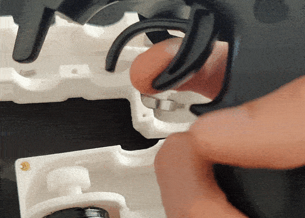
Gifs
Following the block diagram, you should be able to achieve these results.