Summary
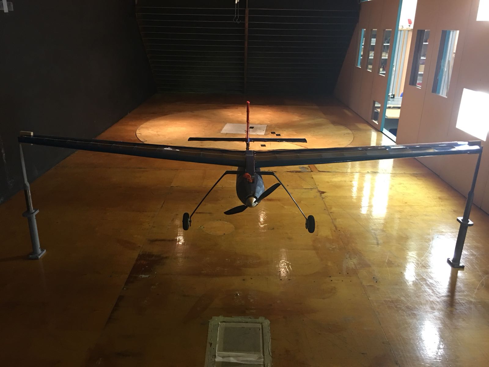
- My elected project for my 4th year in University was to design and build a UAV aircraft. The design requirements were driven out from the 2017 BMFA competition (Payload Challenge).
- The design had to be capable of flying some circuits with varying volumes of water weighing up to 3.5kg.
- As project engineer, I was responsible for coordinating the technical requirements and outputs between our sub-teams.
Aircraft Design Process
-
The aircraft design process used in this project is an adaptation of the design process learnt in university for commercial passenger aircraft design. The design tools and flight mechanic equations developed previously have been repurposed such to fit the requirements for a UAV application.
-
To narrow the focus of our design point, data is collected on other aircraft configurations focused around payload missions. This data collection and market analysis process is a critical element to estimating the conceptual aircraft size and Maximum Take-off Weight (MTOW).
-
The design feasibility relies on estimating a relatively sensible MTOW. It is expected that early MTOW estimates may vary ±20% from the final result, however it is sufficient as a starting point.
-
The entire design process is cyclic and interdependent on other design elements, for example: adjustments in aerodynamic configuration may require a re-assessment of the centre of gravity positioning. There are hundreds of other situations were systems are interconnected and require engineering attention.
-
Beyond the conceptual design, we are relying on emulating design practices within the aircraft model building community in order to achieve a mechanical design that does not add any unnecessary weight.
-
We have elected to stick with a highly conventional configuration which has been tried and tested. The materials involved are mixture between balsa wood, plywood and carbon fibre. This list of materials provide a good strength to weight ratio for the mission we are designing for.
-
Areas of the aircraft which experience high loading (e.g. landing gear, wing root etc.) have been reinforced with plywood and less stressed areas are built with the less dense materials such as balsa to maintain a low overall empty weight.
| Conceptual Design Phase | Detailed Design Phase | |
|---|---|---|
| Aircraft Market Analysis | Aircraft CAD Concept Design | |
| Derive Flight Equations | Preliminary CAD Design | |
| Select Appropriate Design Point | Solidworks Final CAD | |
| Estimate MTOW and OWE | Early Prototyping and Testing | |
| Decide on Aircraft Configuration | Design Revisions and Improvement | |
| Aircraft Centre of Gravity Estimation | Final Manufacturing Output | |
| Aerofoil Comparison and Selection | Electronic Systems Integration | |
| Flight Dynamics Analysis | Systems Validation and Testing | |
| Material Selection | Wind Tunnel Testing | |
| Preliminary Structural Analysis | Flight Test |
Solidworks Design
Exploded View
- Standard water bottle storing main payload in fuselage.
- Supplemented with custom polypropylene wing tanks.
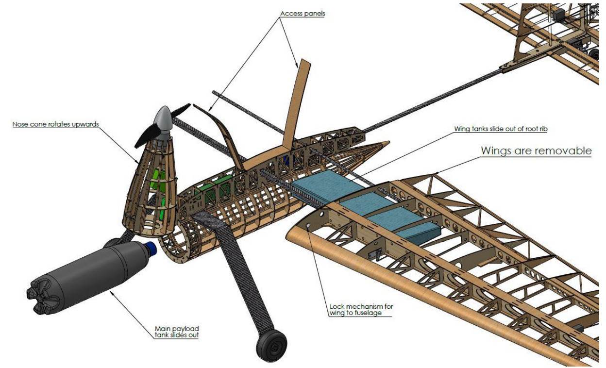
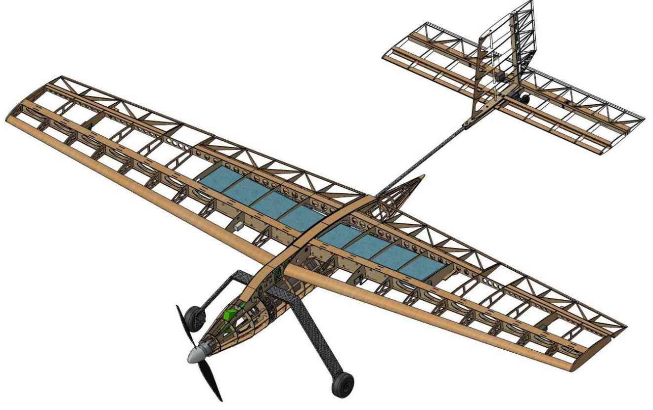
Drawing of UAV Assembly (Final Iteration)
- Conventional aircraft structure with carbon fiber boom connecting tailplane to the fuselage.
Manufacturing
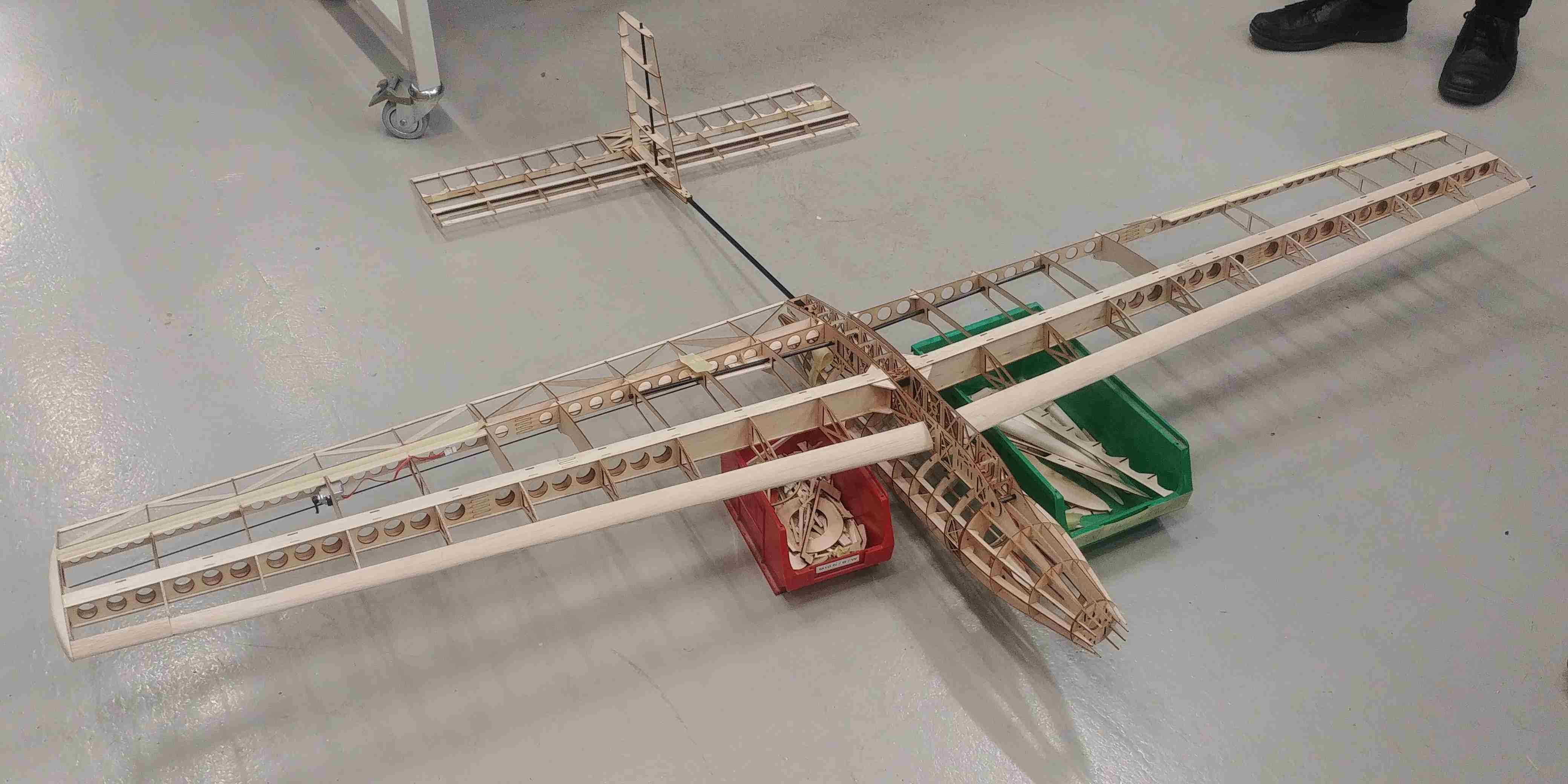
Early Construction of Aircraft
- Constructed with sheets of laser cut balsa and plywood jigsawed together into an assembly.
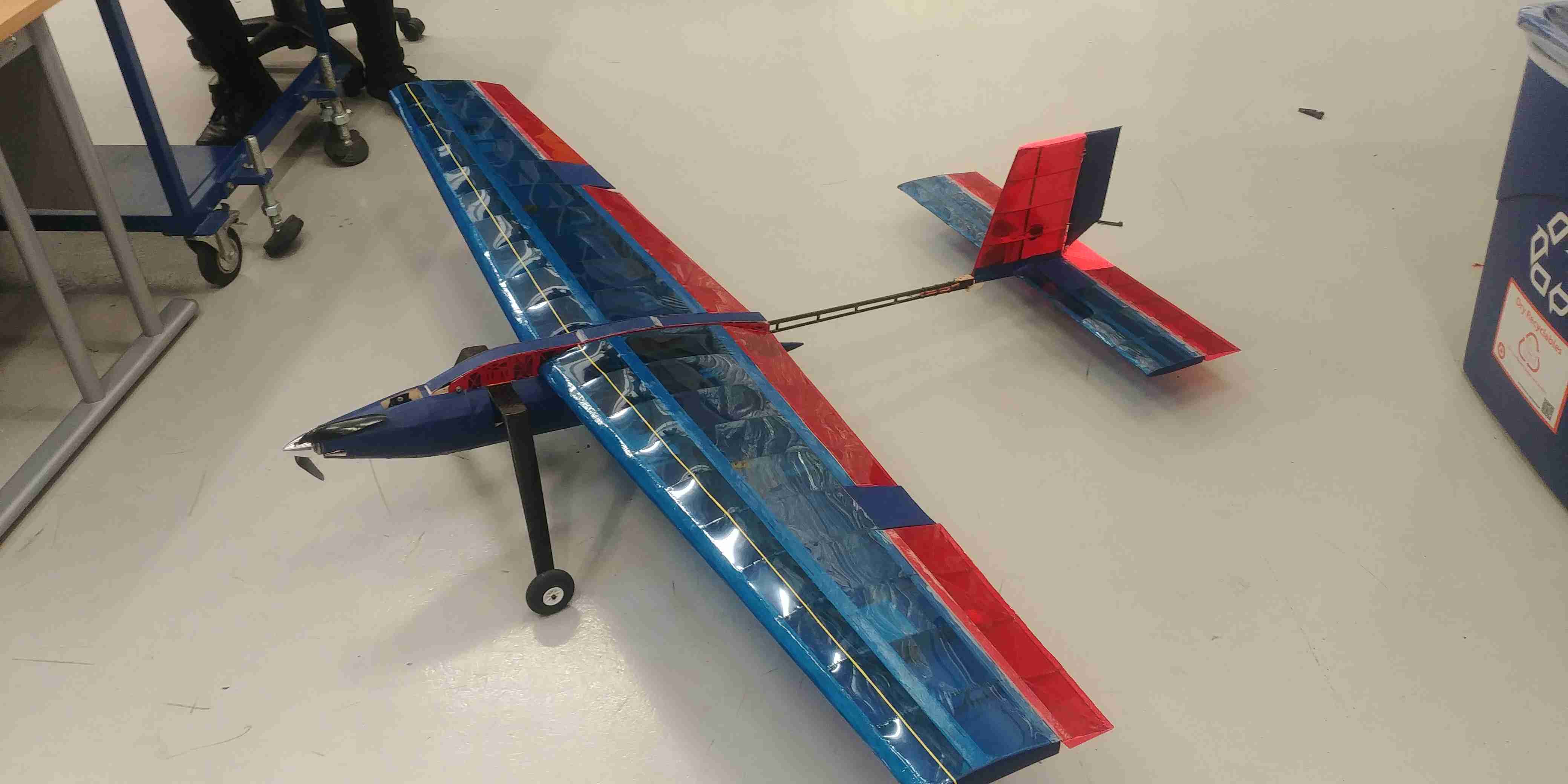
Finalised Construction of Aircraft
- This is the final assembly of the aircraft after gluing/ironing on the skin.
Testing
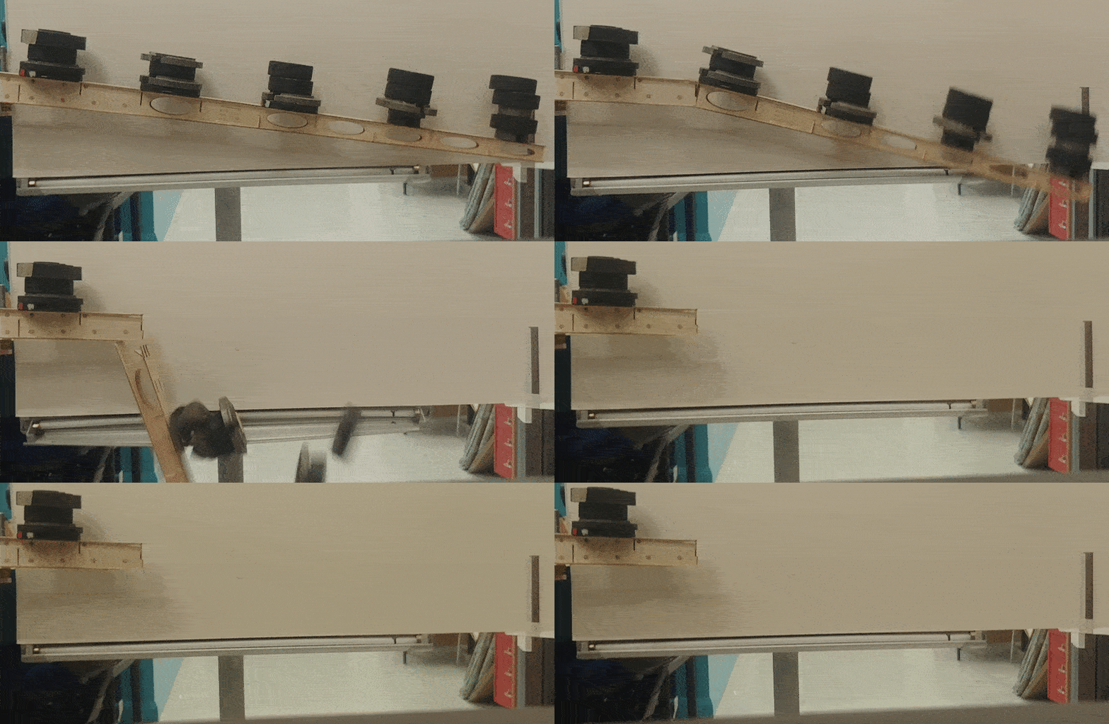
Structural Validation Test - Wing Loading
- Emulated elliptical wind loading distribution on test spar element
- Spar failure at 8kg of wing loading.
 |
|---|
| Simulating Maximum Wing Loading on Spar |
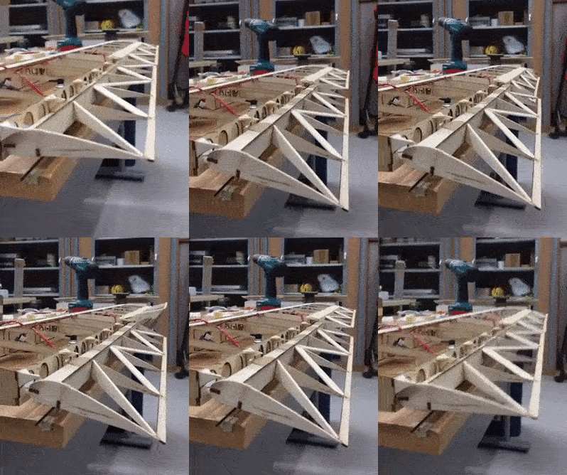
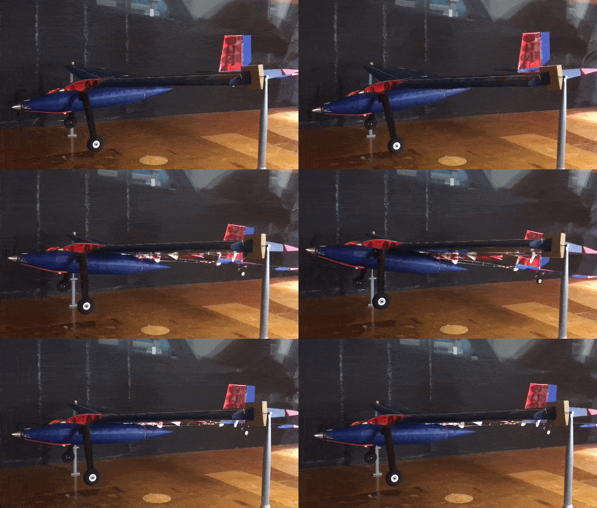
Flight Control Testing
- Installing servos for ailerons and flaps; testing the control mechanisms.
- Flight test to validate aircraft design and measure flight performance.
 |

|
|---|---|
| Flaps and Ailerons | Flight Test |
|
|---|
| Pitch Control |
